10+ avr block diagram
The block diagram of a simple PID controller is provided in the figure below Figure 2. The diagram is shown below.

332 Voltage Regulator Replacement Weekend Freedom Machines
In most applications the control input is not used so that the control voltage equals 23 V CC.

. Above block diagrams are self explanatory. Timing diagram of MVI instruction. 2543mavr1016 attiny2313 block diagram figure 2.
Timing diagram of MOV Instruction in. PID controller design using Simulink MATLAB. I would like to control 12v solar lights.
21 Block Diagram Figure 2-1. Here is the complete circuit diagram for cell phone charger circuit. Advantages and Disadvantages of Microcontroller.
Block diagram of online uninterruptible power supply. Online UPS block diagram. Microchips AVR-IoT Cellular Mini features Sequans Monarch 2 GM02S cellular module.
Satellite communications are related to the space mirrors because they assist us in activating the signals like internet data radio TV from one face of the earth to another face. THATHAS Thinpack Aluminum Electrolytic Capacitors. The block diagram of the satellite communication system includes the following.
Block Diagram of 8259 Microprocessor. The transmitter section includes three blocks namely transmit hold register shift register and also control logic. UART Block Diagram The UART block diagram consists of two components namely the transmitter receiver that is shown below.
I need block daigram and circuit daigram power supply. Likewise the receiver section includes a receive hold register shift register and control logic. Block Diagram The AVR core combines a rich instruction set with 32 ge neral purpose working registers.
I have coming a 8 Channel Relay Module Boards Optocoupler Arduino ARM AVR DSP PIC PLC. The best method used is in the form of an unregulated power supply a combination of a transformer rectifier and a filter. Offline uninterruptible power supply block diagram.
We have used an Arduino Nano for controlling whole this Metal Detector Project. Atmel Studio 7 is the integrated development platform IDP for developing and debugging SMART ARM-based and AVR microcontroller MCU applications. And a resistor for limiting the current to the Arduino pin.
A Coil and capacitor is used for the detection of metals. A LED and Buzzer are used as metal detection indicator. Can I use my relay for testing Safeway.
The Atmel Studio 7 IDP gives you a seamless and easy-to-use environment to write build and debug your applications written in CC or assembly code. Block diagram program counter program flash instruction register gnd vcc instruction decoder control lines stack pointer sram general purpose register alu status register programming logic spi 8-bit data bus xtal1 xtal2 reset internal oscillator oscillator watchdog timer timing and control. Unregulated Power Supply Diagram.
Offline UPS block diagram. One input and meny outputsbut output current will be different. Lets now move towards a simple example regarding the working of a simple PID controller using Simulink.
Timing diagram of INR M. Pin 10 to Pin 17 Port 3. The internal resistors act as a voltage divider network providing 23Vcc at the non-inverting terminal of the upper comparator and 13Vcc at the inverting terminal of the lower comparator.
All the 32 registers are directly connected to the Arithmetic Logic Unit ALU allowing two independent regist ers to be accessed in one single instruction executed in one clock cycle. I have 5v relay songle srd-05vdc-sl-c 10a wemos d1 board. CALL Instructions and Stack in AVR Microcontroller.
In electrocardiography the T wave represents the repolarization of the ventriclesThe interval from the beginning of the QRS complex to the apex of the T wave is referred to as the absolute refractory periodThe last half of the T wave is referred to as the relative refractory period or vulnerable periodThe T wave contains more information than the QT interval. All low power system can be run with a battery. This satellite communication system can be explained through three.
14 Dec 20. Changing the speed of the car is one of the best examples. Refer Block Diagram of 555 timer IC given above.
Followings are the basics difference between them. A signal diode is also used for reducing the voltage. Studio 7 supports all AVR and SMART MCUs.
But for a long time operating devices batteries could prove to be costly and complicated.

Typical Alternator Wiring Voltage Regulator Alternator Diagram

10 Panasonic Car Radio Wiring Diagram Sony Car Stereo Panasonic Car Audio Car Stereo

Schematic Diagram Of The Control Stage Download Scientific Diagram

Arduino Circuit Page 5 Microcontroller Circuits Next Gr

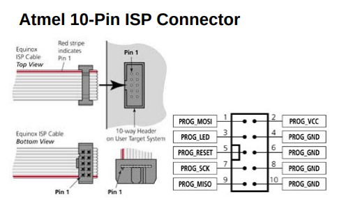
Idc Cable Breakout Board 10 Pin 2x5 0 1 Pmd Way

Schematic Diagram Of The Control Stage Download Scientific Diagram

Capacitor Circuits Capacitor In Series Parallel Ac Circuits Circuit Electronics Circuit Capacitor
The Atmega328p From Almost Nothing

10 Mitsubishi Car Alternator Wiring Diagram Car Alternator Mitsubishi Cars Alternator

10 General Electric Furnace Wiring Diagram Electrical Diagram Electric Furnace Washing Machine Motor

10 Multiple Effect Evaporator Diagram Of Multiple Effect Evaporator Pharmacy Images Medicine Images Free Human Body
Atmega328p Pinout Diagram With Arduino Functions Etechnog

Arduino Nano Pinout Diagram And Specifications Etechnog

Lovely Wiring Diagram Alternator Diagrams Digramssample Diagramimages Wiringdiagramsample Wiringdiagr Electrical Circuit Diagram Voltage Regulator Diagram
Atmega32 Pin Diagram Javatpoint
How Do Avr Microcontrollers Work Quora

Pin On Programming